Hardware Interface
10 minute read
Board Overview
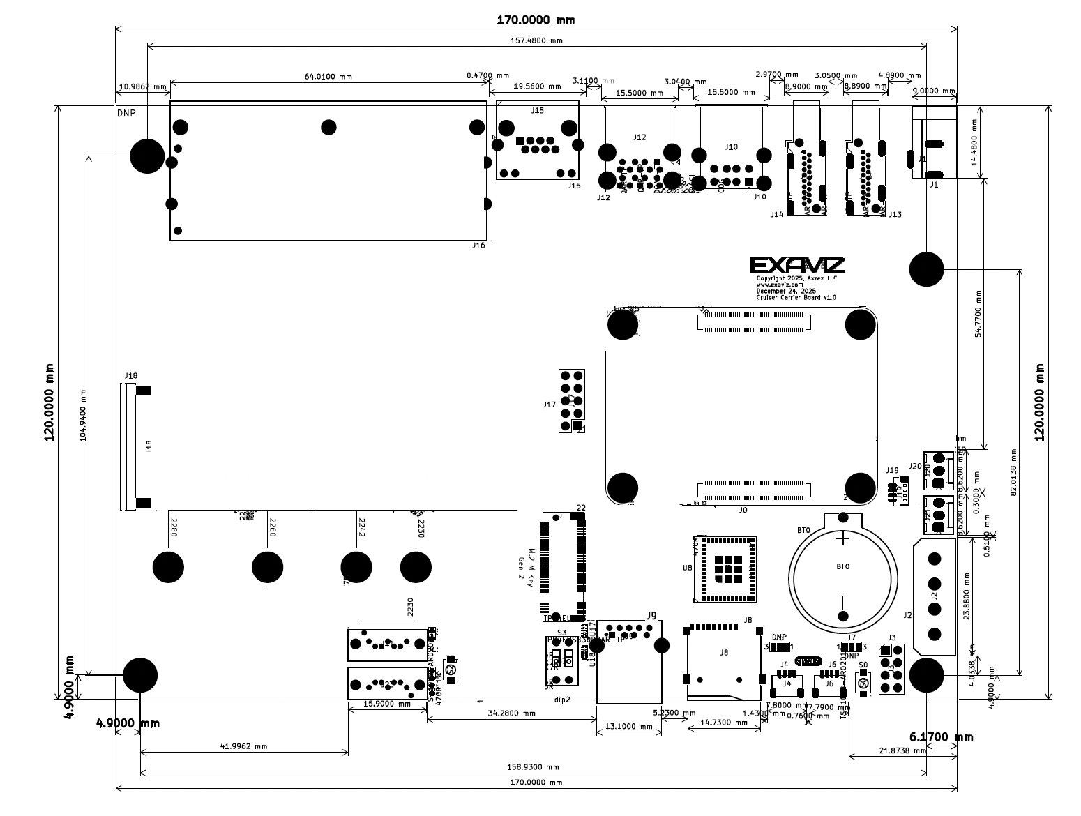
The Cruiser Carrier Board measures 170mm x 120mm and is Mini-ITX compatible with standoff adapters.
Back Panel Connectors
J1 - DC Power Input
48V DC barrel jack (5.5mm outer, 2.1mm inner, center positive).
| Parameter | Value |
|---|---|
| Connector | 5.5mm outer, 2.1mm inner, center positive |
| Absolute Maximum | 57V DC (all models) |
| Maximum Current | 7A |
Voltage requirements by model:
| Model | Minimum | Recommended |
|---|---|---|
| Cruiser / Cruiser Lite | 48V | 48-57V |
| Cruiser Keel (no PoE) | 13V | 24V+ |
PoE models require 48V minimum for IEEE 802.3at PoE+ compliance. The Keel model (no PoE) can operate at lower voltages since it only powers board electronics.
J13, J14 - HDMI Ports
Two full-size HDMI 2.0 ports supporting:
- 4K @ 60Hz (4Kp60)
- Independent dual display
- HDCP 2.2
J10 - USB 2.0 Ports
Stacked dual USB 2.0 Type-A ports.
J12 - USB 3.0 Ports
Stacked dual USB 3.0 Type-A ports (via VL817 hub).
J15 - 2.5GbE WAN Port
RJ45 Ethernet port for network uplink.
| Parameter | Value |
|---|---|
| Controller | Realtek RTL8156BG |
| Speed | 10/100/1000/2500 Mbps |
| Interface | USB 3.0 |
LEDs: The two LEDs in the J15 jack indicate WAN link speed and activity (each is solid when linked and flashes on traffic):
| Link speed | Amber (left) | Green (right) |
|---|---|---|
| 10/100 Mbps | on | off |
| 1 GbE | on | on |
| 2.5 GbE | off | on |
So 1 GbE shows both LEDs, 2.5 GbE shows green only, and 10/100 Mbps shows amber only. The green indicator requires the Exaviz software (the exaviz-netplan package); on a stock operating system without it, green stays off and only amber is shown.
J16 - Gigabit Switch Ports
RJ45 ports in a stacked configuration. Port count and PoE support varies by model.
| Parameter | Cruiser | Cruiser Lite | Cruiser Keel |
|---|---|---|---|
| Ports | 8x RJ45 (2x4) | 4x RJ45 (2x2) | 4x RJ45 (2x2) |
| Speed | 10/100/1000 Mbps | 10/100/1000 Mbps | 10/100/1000 Mbps |
| PoE Standard | IEEE 802.3at (PoE+) | IEEE 802.3at (PoE+) | None |
| Max Power | 30W per port | 30W per port | N/A |
| Switch Chip | 2x RTL8367RB | RTL8367RB | RTL8367RB |
| PoE Controller | 2x TPS23861 | TPS23861 | None |
The Keel model has the same 4-port 1GbE switch as the Interceptor Carrier Board, but without PoE capability. Use it as a standard network switch for non-PoE devices.
Front Panel Connectors
J8 - Micro SD Card Slot
Standard micro SD card slot for boot/storage (CM5 Lite).
J9 - USB 3.0 Port
Single USB 3.0 Type-A port (via VL817 hub).
J4, J6 - Qwiic Connectors
Two Qwiic/STEMMA QT I2C connectors for expansion modules.
| Parameter | Value |
|---|---|
| Connector | JST SH 4-pin |
| Voltage | 3.3V (default) |
| 5V Option | Via solder bridge (intentionally difficult) |
| Protocol | I2C |
Default is 3.3V. Changing to 5V requires modifying a solder bridge. This is intentionally difficult to prevent accidental damage to 3.3V-only devices.
J3 - System Header
8-pin header (2x4, 2.54mm pitch) for front panel connections and serial debug.
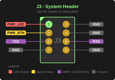
| Pin | Signal | Description |
|---|---|---|
| 1 | PWR_LED | Power LED anode (+). Connect cathode to GND (pin 2). |
| 2 | GND | Ground |
| 3 | PWR_BTN | Power button input. Active low, directly connected to CM5. See the power-on caveat below. |
| 4 | GND | Ground |
| 5 | TXD | UART transmit (GPIO14). 3.3V logic. |
| 6 | RXD | UART receive (GPIO15). 3.3V logic. |
| 7 | GND | Ground |
| 8 | GND | Ground |
Power LED: Connect an LED between pin 1 (anode) and pin 2 (cathode/GND). A current-limiting resistor is already on the board.
Power Button: Directly connected to CM5’s power button input. Directly accessible to software as well.
On the current board revision, pressing the power button will power the unit OFF normally, but with certain HDMI displays it will not power the unit ON from a powered-off state while the HDMI cable is connected. This has been reproduced with some HDMI displays but not others, and is a hardware characteristic of the HDMI +5V supply path, not a software setting. Workaround: unplug HDMI, press the power button to boot, then reconnect the HDMI cable (hot-plug is detected normally). Powering the unit on/off with HDMI disconnected works in all cases. This is slated to be addressed in a future board revision.
Serial Console (UART): Directly connected to CM5’s primary UART (GPIO14/15). Use these pins for headless serial console access during development or debugging.
| Parameter | Value |
|---|---|
| Baud Rate | 115200 |
| Data Bits | 8 |
| Parity | None |
| Stop Bits | 1 |
| Logic Level | 3.3V |
The UART pins are 3.3V logic. Do not connect directly to RS-232 or 5V UART adapters without level shifting. Use a 3.3V USB-to-UART adapter such as the FTDI TTL-232R-3V3.
S0 - Power Button
Onboard tactile button for power control (bench/development use).
Internal Connectors
J0 - CM5 Connector
Two 100-pin board-to-board connectors for Raspberry Pi Compute Module 5.
The Cruiser is designed exclusively for CM5. CM4 modules are not compatible due to different pinouts.
J22 - M.2 NVMe Slot
M.2 Key-M slot for NVMe SSDs.
| Parameter | Value |
|---|---|
| Interface | PCIe Gen 2 x1 (officially) |
| Supported Sizes | 2230, 2242, 2260, 2280 |
| Gen 3 Support | Unofficial (via config.txt) |
CM5 unofficially supports PCIe Gen 3 (~1 GB/s). Add dtparam=pciex1_gen=3 to
/boot/firmware/config.txt to enable. Not officially supported by Raspberry Pi,
but multiple users report reliable operation. See Jeff Geerling’s testing.
M.2 Slot Expansion Options:
The M.2 slot accepts more than NVMe SSDs:
| Type | Example | Notes |
|---|---|---|
| NVMe SSD | Samsung 980 Pro | Primary use |
| AI Accelerator | Hailo-8, Coral TPU | Edge inference |
| SATA Adapter | JMB585-based | +5 SATA ports |
4G/5G cellular modems use M.2 Key-B (30mm width) and will not fit in this Key-M slot (22mm width). For cellular connectivity, use a USB 3.0-based solution. See How can I add cellular connectivity? for recommended options.
J11, J23 - SATA Connectors
Two SATA III (6 Gbps) ports via JMS561 controller.
| Parameter | Value |
|---|---|
| Controller | JMS561 |
| Interface | Dedicated USB 3.0 bus |
| Speed | 6 Gbps (SATA III) |
| RAID | Hardware RAID 0/1/JBOD/SPAN via DIP switch |
SATA drives have their own dedicated USB 3.0 bus from the CM5, not shared with other USB ports. This provides maximum throughput for storage.
J2 - Molex HDD Power
4-pin Molex connector for HDD power.
| Pin | Voltage |
|---|---|
| 1 | +12V |
| 2 | Ground |
| 3 | Ground |
| 4 | +5V |
J17 - USB 2.0 Header
Internal USB 2.0 header (standard 9-pin).
J18 - PoE Expansion (FFC)
40-pin FFC connector for Interceptor PoE Board expansion.
The built-in 8 PoE ports are 1GbE. The Interceptor PoE Board adds 8 ports at 100Mbps (not 1GbE).
See Interceptor PoE Board - Hardware Interface for FFC pinout details.
J19 - CPU Fan Header
4-pin PWM fan header for CPU cooling.
| Pin | Function |
|---|---|
| 1 | Ground |
| 2 | +5V |
| 3 | Tach |
| 4 | PWM |
J20, J21 - Case Fan Headers
Two 3-pin fan headers for case cooling.
| Pin | Function |
|---|---|
| 1 | Ground |
| 2 | +12V |
| 3 | NC |
Buttons and Switches
S0 - Power Button
Onboard tactile button for power on/off. For case builds, use the J3 header to connect an external power button.
S2 - RAID Initialize Button
Press and hold during power-on after changing RAID DIP switch settings to initialize the array in the new mode.
S3 - RAID DIP Switch
2-position DIP switch for hardware RAID mode selection on the JMS561 SATA controller.
| Desired Mode | SW1 | SW2 | Result |
|---|---|---|---|
| JBOD (separate drives) | OFF | OFF | Two independent drives |
| RAID 0 (striping) | ON | ON | Combined volume, ~2x throughput |
| RAID 1 (mirror) | ON | OFF | Redundant, single drive capacity |
| SPAN (concatenation) | OFF | ON | Combined volume, sequential fill |
To change RAID mode:
- Delete any existing array first — The DIP switches only configure a new array when no array exists. Use the software tool to delete the current array (see JMicron RAID Manager for installation):
sudo raidmgr_static # At the JMS56X> prompt, type: DR C0 R0 # Then type: EX - Power off the board completely
- Set DIP switches to the desired configuration (see table above)
- Press and hold the RAID Initialize button (S2)
- Power on while continuing to hold the button for 5 seconds
- Release button — the new RAID mode is now active
Changing RAID mode will destroy all data on the connected SATA drives. Back up any important data before reconfiguring.
RAID can also be configured via software using the raidmgr_static tool without power cycling. See Software - JMicron RAID Manager for details. Note: SPAN mode is only available via hardware DIP switches.
LEDs
| Reference | Color | Function |
|---|---|---|
| D2 | Blue | Standby. Board 5V rail present, independent of the compute module |
| D3 | Yellow | Power On. Compute module rail is up |
| D4 | Green | System activity. Driven by the compute module while it is running |
| D5 | Green | M.2 activity. Its rail is enabled by the compute module |
| D14 | Green | SATA Port 1 Activity (J11) |
| D15 | Green | SATA Port 2 Activity (J23) |
| D16 | Green | Ethernet activity. Driven by the compute module while it is running |
| J15 (Left) | Amber | WAN link / activity at 10/100 Mbps and 1 GbE (solid when linked, flashes on traffic) |
| J15 (Right) | Green | WAN link / activity at 1 GbE and 2.5 GbE (requires the Exaviz software) |
Reading the board LEDs
The indicators light in stages, and the stage that fails tells you where to look. D2 is the only one powered directly from the board’s own 5V rail. Every other indicator depends on the compute module being powered, running, or both.
| What you see | What it means |
|---|---|
| Nothing lit at all | No input power reaching the board, or the 5V rail is down. Check the supply and the barrel jack or PoE source first |
| D2 only | The board’s own power is good and the compute module is not powered. Its rail never came up. The board is not the first suspect - look at the module and its connectors |
| D2 + D3 | The compute module is powered. Whether it has started is a separate question - see the note below |
| D2 + D3 + D4 or D16 | The compute module is powered and running. D4 or D16 lighting is positive proof it is alive |
Three cautions when reading these:
- D4 and D16 prove liveness in one direction only. They are activity indicators, driven by the compute module for storage and Ethernet traffic. If either is lit the module is certainly running, but an idle module with no disk or network traffic can leave both dark. Do not read dark D4 and D16 as proof the module has not started - confirm with the network or a display before concluding that.
- D2 is the highest-brightness-threshold indicator on the board. It dims and then goes out while the 5V rail is still partly up, so a dark D2 means the rail is low, not necessarily absent. A photograph cannot tell those apart. If it matters, measure the rail rather than judging by eye.
- The compute module has its own LED, separate from these. It reports the module only and says nothing about the board’s rails. A lit module LED next to dark board LEDs is a normal-looking combination, not a contradiction.
If you land on D2 only, or on nothing at all, continue with Board won’t power on.
ESP32-C6 Module (U8)
Built-in ESP32-C6 for wireless connectivity.
The ESP32-C6 has a single 2.4 GHz radio shared by WiFi, Bluetooth, and Zigbee. A Zigbee coordinator has to listen continuously, which Espressif rates as unsupported alongside a WiFi access point and unstable alongside a WiFi client. The module therefore runs either the factory WiFi + Bluetooth firmware or the Zigbee coordinator firmware (beta) - not both at once. See the ESP32 Wireless Module page.
Note: Thread, Matter, and 802.15.4 are not supported by Exaviz firmware. See the ESP32 documentation for custom firmware options.
| Feature | Specification |
|---|---|
| WiFi | 802.11ax (WiFi 6), 2.4 GHz (WiFi + Bluetooth firmware) |
| WiFi Interface | SDIO (~200 Mbps) |
| Bluetooth | LE 5.3 (via UART) (WiFi + Bluetooth firmware) |
| Zigbee | Coordinator via ESP32-C6 (separate beta firmware) |
ESP32 Control GPIOs:
- GPIO16: EN (reset/power cycle)
- GPIO17: BOOT mode (firmware updates)
Other Components
BT0 - RTC Battery
CR2032 battery holder for real-time clock backup.
DNP - Chassis Ground Bridge
0Ω resistor location for chassis-to-digital ground connection.
| Chassis Type | Configuration |
|---|---|
| Metal | Leave unpopulated (ground via case) |
| Plastic | Populate 0Ω resistor |
Mechanical Specifications
| Parameter | Value |
|---|---|
| Dimensions | 170mm x 120mm |
| Form Factor | Mini-ITX compatible* |
| Mounting Holes | 4x M3 (see table below) |
*Requires standoff spacers. Mounting holes do not align with standard Mini-ITX pattern.
Board dimensions: 170.0mm × 120.0mm
| Corner | Distance from Nearest Edge |
|---|---|
| Top Left | 6.35mm from left, 10.16mm from top |
| Top Right | 6.17mm from right, 33.02mm from top |
| Bottom Right | 6.17mm from right, 4.9mm from bottom |
| Bottom Left | 4.9mm from left, 4.9mm from bottom |
Note: Bottom left corner matches Mini-ITX standard (4.9mm from edges). Other corners are non-standard. Use board dimensions above to calculate distances from other edges as needed.
Source: CAD design files (source of truth for mechanical specifications).
Last modified October 11, 2026