Hardware Interface
2 minute read
Board Layout
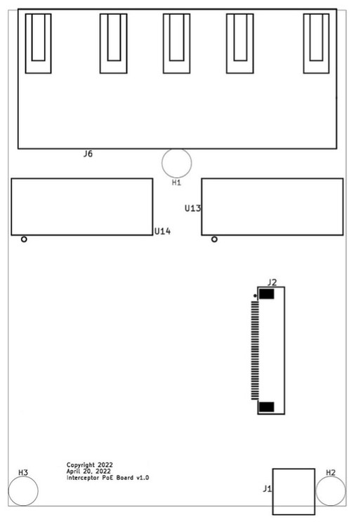
Connector Reference:
- J6 - Eight port RJ-45 switch
- U13, U14 - Ethernet magnetics
- J2 - FFC (40 pos) connection to carrier board
- J1 - PoE power input (48V DC)
- H1, H2, H3 - Mounting holes
Connectors
J1 - Power Input (Terminal Block)
48V DC power input from VOITA converter.
| Terminal | Signal |
|---|---|
| + | +48V DC |
| - | Ground (GND) |
Ensure correct polarity when connecting the VOITA converter. Reverse polarity may damage the board.
J2 - FFC Connector (40-pin)
Connection to Interceptor Carrier Board (J9 or J10).
| Parameter | Value |
|---|---|
| Type | 40-pin FFC/FPC |
| Pitch | 0.5mm |
| Orientation | Contacts up, blue reinforcement tape down, printing visible on top |
Insert the FFC cable evenly and deep. Most of each contact should be inside the connector, though the back portion of each contact may be partially visible. What matters is that all contacts are inserted to the same depth—if one side is deeper than the other, reseat the cable. Even and deep is key. Locked in.
If you do not have it locked in and move the cable while powered on, it can burn out the cable and make it useless.
J6 - Ethernet Ports (8-port)
Eight RJ-45 ports with PoE injection.
| Port | Interface (Board 1) | Interface (Board 2) |
|---|---|---|
| 0 | poe0 | poe8 |
| 1 | poe1 | poe9 |
| 2 | poe2 | poe10 |
| 3 | poe3 | poe11 |
| 4 | poe4 | poe12 |
| 5 | poe5 | poe13 |
| 6 | poe6 | poe14 |
| 7 | poe7 | poe15 |
The interface name depends on which carrier board connector the PoE board is attached to:
- J9 → Board 1:
poe0throughpoe7 - J10 → Board 2:
poe8throughpoe15
Dual Board Port Numbering
When using two PoE boards:
| Board | Carrier Connector | Ports | Interfaces |
|---|---|---|---|
| Board 1 | J9 | 0-7 | poe0-poe7 |
| Board 2 | J10 | 8-15 | poe8-poe15 |
Port Layout
The board is designed to stack alongside or above the carrier board:
Port Layout (2x4 configuration):
┌───┬───┬───┬───┐
│ 0 │ 2 │ 4 │ 6 │  ← Top row
├───┼───┼───┼───┤
│ 1 │ 3 │ 5 │ 7 │  ← Bottom row
└───┴───┴───┴───┘
Last modified April 9, 2026