Hardware Interface
4 minute read
This page provides detailed pinout information for all connectors on the Interceptor Carrier Board v2.0.
Board Layout Overview
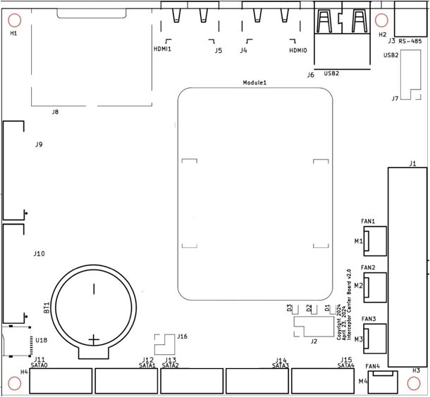
The board layout (100mm × 110mm) has the following major areas:
- Rear I/O - HDMI (J4, J5), USB (J6), Ethernet (J8)
- Power Section - ATX connector (J1), fan headers (M1-M4)
- Storage - SATA connectors (J11-J15)
- Expansion - FFC connectors for PoE boards (J9, J10)
- Compute Module - Central location (Module1)
- Front Panel - Power button, LEDs, serial (J2)
J1 - ATX Power Connector (24-pin)
Standard ATX 24-pin power connector. Compatible with 20-pin PSUs (pins 11-14, 23-24 optional).
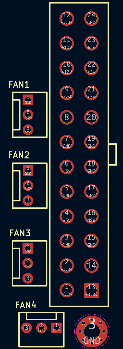
| Pin | Signal | Pin | Signal |
|---|---|---|---|
| 1 | +3.3V | 13 | +3.3V |
| 2 | +3.3V | 14 | -12V |
| 3 | GND | 15 | GND |
| 4 | +5V | 16 | PS_ON# |
| 5 | GND | 17 | GND |
| 6 | +5V | 18 | GND |
| 7 | GND | 19 | GND |
| 8 | PWR_OK | 20 | NC |
| 9 | +5VSB | 21 | +5V |
| 10 | +12V | 22 | +5V |
| 11 | +12V | 23 | +5V |
| 12 | +3.3V | 24 | GND |
Ensure your PSU provides a stable +3.3V rail. Voltage drops below 3.2V will cause the Raspberry Pi to crash or behave erratically.
J2 - Front Panel Header (8-pin)
The front panel header provides connections for power button, power LED, and UART.
| Pin | Signal | Description |
|---|---|---|
| 1 | LED+ | Power LED Positive (Green wire) |
| 2 | LED- | Power LED Negative (Black wire) |
| 3 | PWR_BTN | Power Button (Red wire) |
| 4 | PWR_BTN | Power Button (White wire) |
| 5 | UART_TX | Serial Transmit (3.3V TTL) |
| 6 | UART_RX | Serial Receive (3.3V TTL) |
| 7 | GND | Ground |
| 8 | GND | Ground |
Pin Orientation: Pins 1 & 2 are at the bottom left of the header.
UART Configuration
- Baud Rate: 115200
- Data Bits: 8
- Stop Bits: 1
- Parity: None
- Flow Control: None
Use a 3.3V USB-to-Serial adapter. Do not use 5V logic - this will damage the compute module.
J3 - RS-485 Connector (3-pin)
Industrial serial communication interface.
| Pin | Signal |
|---|---|
| 1 | A (Data+) |
| 2 | B (Data-) |
| 3 | GND |
J4 & J5 - HDMI Ports
Two full-size HDMI 2.0 connectors supporting up to 4K @ 60Hz.
- J4 - HDMI0 (Primary)
- J5 - HDMI1 (Secondary)
When using Banana Pi CM4, only J4 (HDMI0) is functional.
J6 - Rear USB 2.0 Ports
Two USB 2.0 Type-A ports for peripherals.
| Port | Speed |
|---|---|
| USB1 | 480 Mbps |
| USB2 | 480 Mbps |
J7 - USB 2.0 Header (9-pin)
Internal header for additional USB 2.0 ports (standard motherboard pinout).
| Pin | Signal | Pin | Signal |
|---|---|---|---|
| 1 | +5V | 2 | +5V |
| 3 | D- | 4 | D- |
| 5 | D+ | 6 | D+ |
| 7 | GND | 8 | GND |
| 9 | Key | - | - |
J8 - Gigabit Ethernet Switch (4-port)
Four RJ-45 ports connected to the RTL8367RB managed switch.
Port Layout (2x2 configuration):
 ┌─────┬─────┐
 │  B  │  D  │  ← Top row
 ├─────┼─────┤
 │  A  │  C  │  ← Bottom row
 └─────┴─────┘
   Left  Right
| Port | Position | Default Role | Speed |
|---|---|---|---|
| A | Bottom-left | WAN (receives IP from upstream network) | 10/100/1000 |
| B | Top-left | LAN (DHCP server provides IP) | 10/100/1000 |
| C | Bottom-right | LAN (DHCP server provides IP) | 10/100/1000 |
| D | Top-right | LAN (DHCP server provides IP) | 10/100/1000 |
By default in Exaviz OS, Port A is the WAN port (client mode - receives IP from your network). Ports B, C, and D are LAN ports where the Exaviz OS DHCP server assigns IP addresses to connected devices.
Each port has integrated LEDs for link status and activity.
J9 & J10 - FFC Connectors (40-pin)
Flat Flexible Cable connectors for Interceptor PoE Board expansion.
| Connector | Description |
|---|---|
| J9 | PoE Board 1 (interfaces poe0-poe7) |
| J10 | PoE Board 2 (interfaces poe8-poe15) |
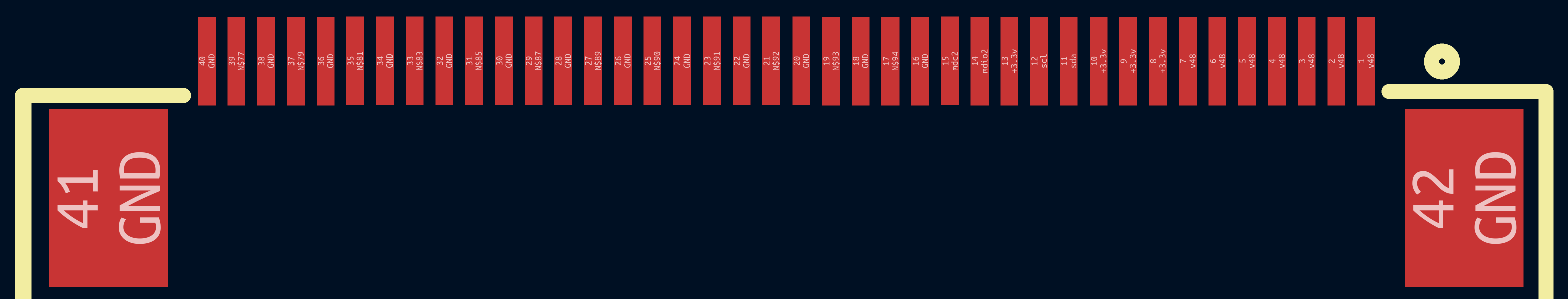
Note: The pinout diagram shows J10, but J9 has the same structure. Data trace numbering differs between connectors, but power, ground, and signal assignments are identical.
Cable Installation:
- Pull the locking clips outward
- Insert the FFC cable with contacts up (printing visible on top), blue reinforcement tape down
- Push clips inward to lock
Ensure cables are fully seated. Poor connections can cause intermittent PoE issues.
J11 - J15 - SATA Connectors
Five SATA III connectors for storage drives.
| Connector | Port Number | Controller |
|---|---|---|
| J11 | SATA 0 | JMB585 |
| J12 | SATA 1 | JMB585 |
| J13 | SATA 2 | JMB585 |
| J14 | SATA 3 | JMB585 |
| J15 | SATA 4 | JMB585 |
All ports support hot-plug and 6 Gbps transfer rates.
M1 - M4 - Fan Connectors (3-pin)
Four 12V fan headers for case/drive cooling.
| Pin | Signal |
|---|---|
| 1 | GND |
| 2 | +12V |
| 3 | Sense (tachometer) |
PWM speed control is not supported. Fans will run at full speed when connected.
U18 - Micro SD Card Slot
Located near the compute module socket. Supports microSD cards up to 512GB (tested).
BT1 - RTC Battery
CR2032 (3V) coin cell battery holder for real-time clock backup.
Compute Module Socket
Two high-density connectors for Raspberry Pi CM4/CM5 or compatible modules.
- 200-pin connector - Primary interface
- Alignment notches prevent incorrect installation
- Press firmly until module clicks into place
Next Steps
- Getting Started - Initial setup guide
- Software - OS configuration and drivers
- Specifications - Complete technical specs
- Expansion - PoE board installation
Last modified April 9, 2026