PoE Port Management
5 minute read
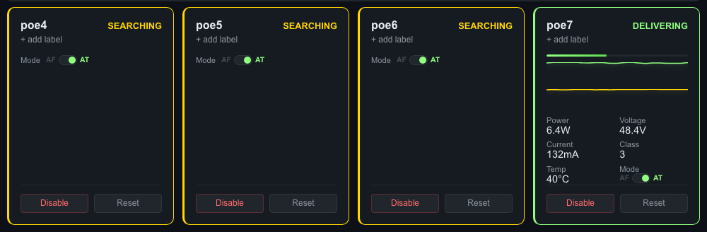
PoE port tiles showing four ports on PSE 0. Port 3 (“Server Switch”) is delivering power with real-time metrics. Ports 0-2 are searching for devices.
Port Layout
PoE ports are displayed as tiles arranged to match the physical board layout:
- Top row - Even-numbered ports (poe0, poe2, poe4, poe6)
- Bottom row - Odd-numbered ports (poe1, poe3, poe5, poe7)
On Cruiser boards with 8 ports, there are two PSE controllers (PSE 0 and PSE 1), each managing 4 ports. The dashboard labels each section.
Port Status
Each port tile displays:
| Field | Description |
|---|---|
| Port name | Hardware name (poe0, poe1, etc.) and custom label if set |
| State | Current power state (see table below) |
| Power (W) | Real-time power draw in watts |
| Voltage (V) | Port voltage |
| Current (mA) | Port current draw |
| Temperature (C) | PSE temperature for this port |
| Class | PoE device class (0-4) |
| Mode | PoE standard (at = PoE+ 30W, af = PoE 15.4W) |
Port States
| State | Meaning | Color |
|---|---|---|
| Delivering | Actively powering a connected device | Green |
| Searching | Looking for a PoE device on the port | Yellow |
| Disabled | Power manually turned off | Gray |
| Fault | Error detected (overcurrent, short circuit, etc.) | Red |
| Backoff | Temporary retry period after a fault | Orange |
Here is a closer look at a single port tile when a device is connected:
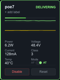
Port 3 delivering 6.3W to “Server Switch.” Power, voltage, current, class, temperature, and PoE mode are all visible. Sparklines at the top show the last hour of power and temperature history.
Sparklines
Each port tile includes small graphs showing the last hour of power and temperature data (60 samples at 1-minute intervals). Hover over the sparkline to see exact values at a point in time.
Controlling Ports
Each port tile has three control buttons:
Enable / Disable
Toggle power delivery on a port. When you disable a port, power is cut immediately. When you enable a port, the PSE begins the detection and classification process to discover and power the connected device.
Reset
Power-cycles the port: disables power, waits briefly, then re-enables. Use this to recover a device that has stopped responding. The connected device will reboot.
Resetting a port will temporarily interrupt the connected device. IP cameras, access points, and other PoE devices will reboot and may take 30-60 seconds to come back online.
Mode Switching
Toggle between PoE+ (at, 30W max) and PoE (af, 15.4W max) per port. The port briefly power-cycles during the switch. Class 4 devices (those requesting more than 15.4W) require AT mode.
Connected Device Identification
When a PoE device is connected and receiving power, the dashboard automatically identifies it. Below the port label, you will see:
- Manufacturer - Identified from the device’s MAC address (e.g., “Axis”, “Ubiquiti”, “Hikvision”)
- IP address - The device’s IP on your network
- Hostname - The device’s DNS name (if available)
- MAC address - Visible in the tooltip for full details
For example, a port tile might display: “Axis Camera - 10.0.1.100 - axis-cam-01.local”
This makes it easy to know exactly what is on each port without tracing cables or maintaining a spreadsheet.
Port Labels
Assign a custom name to any port to identify the connected device:
- Click the port label area on a port tile (or the edit icon)
- Type a descriptive name (e.g., “Lobby Camera”, “AP Floor 2”, “Front Door”)
- Save
Labels appear on the port tile, in fleet view, and in alert messages. They persist across reboots and are included in backups.
Port Groups
Port groups let you apply operations to multiple ports at once.
Creating a Group
- Scroll to the Port Groups section below the port tiles
- Click + New Group
- Enter a group name (e.g., “All Cameras”, “Floor 1 APs”, “Conference Room”)
- Select the ports to include
- Save
Group Operations
Once a group is created, you can:
- Enable all - Turn on power to every port in the group
- Disable all - Cut power to every port in the group
- Reset all - Power-cycle every port in the group
Use Cases
- “All Cameras” - Enable or disable all security cameras at once
- “Floor 1” - Manage all devices on a specific floor
- “Maintenance” - Group ports that need periodic resets
Groups are stored locally on the board and included in backups.
PoE Standards Reference
| Standard | Marketing Name | Max Power Per Port | Device Classes |
|---|---|---|---|
| IEEE 802.3af | PoE | 15.4W | 0, 1, 2, 3 |
| IEEE 802.3at | PoE+ | 30W | 0, 1, 2, 3, 4 |
Device Classes
| Class | Max Power | Typical Devices |
|---|---|---|
| 0 | 15.4W | Default (device does not advertise class) |
| 1 | 4.0W | VoIP phones, simple sensors |
| 2 | 7.0W | IP cameras (low power), card readers |
| 3 | 15.4W | IP cameras (standard), wireless APs |
| 4 | 30W | PTZ cameras, high-power APs, displays |
Troubleshooting
Port stuck in “Searching”
The port is looking for a PoE device but not finding one. Check:
- Is a PoE-capable device connected to the port?
- Is the Ethernet cable good? Try a different cable.
- Some devices only negotiate on specific pairs. Ensure you are using a proper Cat5e or Cat6 cable.
Port in “Fault” state
The PSE detected an error. Common causes:
- Short circuit in the cable or device
- Device drawing more power than the port class allows
- Overtemperature on the PSE controller
Try resetting the port. If the fault persists, check the cable and connected device.
Port in “Backoff” state
The PSE is in a retry period after a fault. It will automatically attempt to reconnect. If the port keeps cycling between backoff and fault, there is likely a hardware issue with the cable or connected device.
Last modified April 9, 2026